beer rev limiter instal to toyota ecu wiring diagram
Link to post Share on other sites. R34 Gtt Find best value and selection for your Bee R Rev Limiter Subaru Nissan Toyota Mitsubishi dsm search on eBay.

Bee R Rev Limiter Instructions Inside Toyota Gt Turbo
I bought this as a rev limiter the others are just bonus goodies Adjustable Limiter set it lower look im not here for an argument im just here for info that I need to finish my install back on topic Hmm alright so I found-Vehicle speed sensor 83 for yellowconfirmed that I have this wire-64 eninge speed out put I do not have.

. The following pin and color wire. Describe the meaning of the 2 in diagram component S. Posted September 28 2005.
I have coloured each pin to match the Bee-R wire colours. 3 there are three screws that need to be removed in order to get to the ecu. I forget that everyone had to start somewhere myself included Here is a list of every Toyota abbreviation I could find.
Modal semi trailer wiring diagram for 4S3M and 6S3M. Toyota Ecu pinout abbreviations. Base on the BeeRacing Rev Limiter installation manual itself.
White with red stripe from ECU Pins 12 B and 13 B1 on the E7 harness connector. 2 the ecu is located on the passenger side directly where your foot would rest if you were sitting down. It has a rev limiter.
Fuel cut as used on many standard vehicles risks damage to high performance engines when at high revs. Its pin 11 connector A for prefaceliftobd2a and pin 1 connector B for faceliftobd2b. According to what Ive been reading it seems the yellow wire gets hooked up to IGF between the ECU and ignitor.
I was asked to define the abbreviations of what I thought everyone would know. Describe and identify the diagram component U. 1 toyota tacoma electrical wiring diagram a 22 3e at 2 mt 2 acc ig1 st1 ig2 mt am1 b-w 1 7am2 6 w-r 22 w b 22 b- w 20 3e 6 3e 4 ea1 21 if1 8ik3 w 22 21 3e 7 3e 10 3e b- w b- y b-w w- r 9 6 2 2 5 3e 8 3e 21 ik2 ie 16 3a 2 1 1a.
Should only be installed by an experienced mechanic. Describe the meaning of the SD in diagram component T. 4 Sep 17 2014.
Your wiring will look like this after you have completed the wiring of the bee r rev limiter. The green wire coming off the beer u have to solder on two wires each with a 1000v 1A diodes make sure the silver side is facing the beer. 3 Disconnect the ECU plug and locate the correct wires using the diagram below.
If there is anything missing or incorrect please feel free to share. Bee r rev limiter problems i hooked my bee r rev limiter like the diagram and now the car doesnt start for the car to start i have to wire the ignition unit wire like it was before if someone can help i will appreciate. This is their simple.
Diodes are used to keep the 4 ignition signals separate. Red top SR20DET user should use diagram N02 also. 1first thing you need to do is disconnect the positive battery terminal.
W2 aux and or e emergency wiring connections will normally connect to the ecobee3 w1 terminal. JZ Swap and Wiring shared. There is a fitting guide available for the Bee-R rev limiters on the Bee-R website but its all in Japanese which poses a problem for the non Japanese fluent amongst us.
The wiring harness ecu and motor are all from the same vehicle. If when the car is all back together and it wont start swap the greenyellow. Describe the meaning of the C13 in the diagram component Q.
The rev limiter on a car is there to prevent over-reving which will destroy the engine. See manual attached to confirm Type B Type H and Type. Older cars use one ignition signal wire controlled ground for the system.
Joined Aug 15 2008 Messages 274. Double sided tape etc. I was able to find a wiring diagram in eBay for my classic car a Ford 1979.
Any Additional wiring information would be great ps. Joined Sep 9 2009 Messages 284. Dec 25 2009 7.
Basic Help Repair. Part 2 1 on the controller cut the gray wire. You will be looking for IGP1 Power source pin at the ecu.
PART 2 1 On the controller cut the gray wire for 4 cylinder applications. The green and yellow are already reversed on this diagram as it seems the Bee-R diagram is wrong for most cars. Haldex ABS Modal ECU wiring diagrams.
1112014 You cant over rev with the stock ecu. That would be connector E7 pin 7 blackblue stripe on the ECU. I installed this on a ej20k here is my wiring diagram.
June 26 2013. Red E10A Pin31 40 pin connector this is the B ECM main relay pin Black Chasis ground Green E9B Pin27 80 pin connector this is the NE crank position sensor pin Yellow E9B Pin58 80 pin connector this is the IGF ignitor pin. Also on the 34 ECU the is 4 groups of pinouts My 34 wiring harness only has 3 plugs is the fourth plug on the 99 4runner the motor came from.
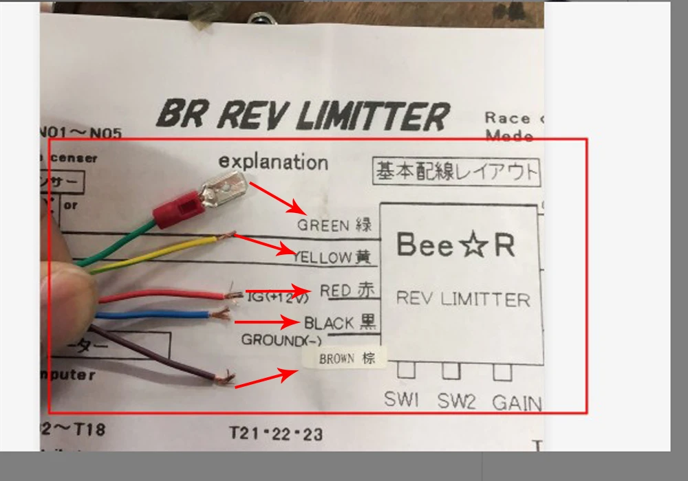
Silvias and Starlets being some that have been discovered to be wrong. Anyway this is the diagram that Bee R supplies. Right i bought the superchips icon but the instructions i got with it dont match with my ECU.
Think of a diode as a check valve for electricity. Ignition cut is used in F1 WRC and other forms of motorsport. The bee-r keeps the coil grounded preventing the secondary from firing the plug.
Bee r rev limiter wiring diagram toyota. The Bee Racing Rev Limiter is suitable for a large range of vehicles. Joined Aug 24 2012.
This is the instuctions in japanese please use it to work out the correct wiring plug arrangement for your car. So am looking ECU wiring diagrams for the ST202 3S-GE enginei looked at the online manuals at the top of the forum but its only american engines it lists in there. Your wiring will look like this after you have completed the wiring of the BeeR Rev Limiter.
An expert whose answer got voted for 2 times. Bee R rev limiter. Control ecu from abs actuator with ecu db ea b- r b b j11 junction connector c10.
Then u solder those two wires on to both ignitors see my wiring sheet Save. BeeR Ignition Rev Limiter Fitting English Instructions. Remove the trim covering the ECU in the passenger foot well use the correct side.
Without more specifics I can only piece together this based on my diagrams for my 93. The two wire tie in before junction I15 and then off to circuits like the Cold start injector Circuit o2 sensor circuit ac idle up circuit Circuit opening relay circuit EFI main relay Circuit. 1970 dodge charger wiring diagram manual 70 9 00 picclick pdf.
Beer Rev Limiter Wiring Help. You need to go to eBay and try to find the wiring diagram or contact dealer on your area. Describe the meaning of the G-W in diagram component R.
It turns out as we suspected that Bee R supplies incorrect wiring diagrams for some cars. The wrx has coil on plug thus 4 separate ignition signal wires. UNDERSTANDING TOYOTA WIRING DIAGRAMS WORKSHEET 1 1.
Modal ECU connector and power supply details. Did you get any wiring diagram with the r rev limiter.
Help With Connection Bee R To 1zz Fe Driftworks Forum

Diy Bee R Install 2step Lexus Is Forum
Bee R Rev Limiter 1zz Fe Problem Driftworks Forum
Car Modification New Power Manufacturer Racing Type B Rev Limiter Release Control Exhaust Pipe Ignition Device Flame Kit Electronic Ignition Aliexpress

Auto Performance Parts Auto Parts Accessories Bee R Rev Limiter Type B Launch Control Subaru Mitsubishi Mazda Nissan Toyota
Bee R Rev Limiter Problems Please Help Scoobynet Com Subaru Enthusiast Forum

Help Installing Bee R Rev Limiter Toyota Yaris Forums Ultimate Yaris Enthusiast Site

How To Install Bee R Rev Limiter K20 F20 Honda Acura K20a K24a Engine Forum

Racing Power Builder Type B Flame Kits Exhaust Ignition Rev Limiter Launch Control For Nissan Subaru Toyota Yc101502 Aliexpress Automobiles Motorcycles
Bee R Rev Limiter Fitting Guide Driftworks Forum
Bee R Help Driftworks Forum

Beer Rev Limiter Honda D Series Forum
Looking For A Diagram To Wire A Bee R To My Ecm Scoobynet Com Subaru Enthusiast Forum

Wiring Bee R Rev Limiter Honda D Series Forum

Bee R Power Builder Need Help Subaru Impreza Gc8 Rs Forum Community